
Yes sorry, one more to add to the Internets long lineup of ramps documentation.
We have been requested to document the ramps setup specific to the Ordrbot sold at www.3DTek.xyz. If you have another form of 3D printer you can probably read along anyway although not all will be relevant. This is a beginners guide so if you already know… move on;)
Shortcuts to info:
Identifying components
A closer look at Stepper Motors
A closer look at Stepper Drivers
A closer look at Arduino Mega 2560 & Clones
A closer look at Ramps 1.4 Shield
A closer look at Reprap LCD Controller and associated paraphernalia
Wiring
Assembling the Electronics
Identifying components
Starting from the basics, lets identify the electronics you will be configuring.
- Stepper Motors

- Stepper Drivers

- Arduino Mega 2560 & Clones

- Ramps 1.4 Shield

- Reprap LCD Controller and associated paraphernalia

A closer look at Stepper Motors
The image below shows a fairly typical (yet maybe more powerful than usual for a 3d printer) NEMA17 stepper motor.
3DTek.xyz use a larger 1.7A, 62 Ounce Inch stepper as the Ordbot is much more rigid than most and can handle having the carriages thrown around at break neck speed. Those supplied by 3DTek.xyz also have approx. 2m of wire (rather than the usual 15cm) so you don’t have to extend them.

The NEMA 17 is a dimensional standard, so if you have one NEMA 17 motor it will usually bolt in place of another. However the depth of the motor is dependent on the Ounce inch holding torque rating and manufacturing.

Most steppers (we use) have 200 steps per revolution – that is to say there is 200 detents or positions that the motor can with some accuracy move to or stop/hold at per revolution. If this interests you Google about micro stepping and its pros/cons.
The most important part of using a stepper is finding out which are the two pairs in those 4 wires. The 3Dtek.xyz supplied motors use Black / Green as one pair and Blue / Red as the other. If you don’t know what your pairs are on the motor your using, grab a multi-meter and set it to continuity or a low resistance setting. Test against any combination of two wires until you get a beep or a resistance value similar to that of the data sheet for your motor – Hooray that’s one pair! Test the other two as well but you can also assume they are the other pair.
Its important to work out these pairs as failing to correctly connect your motor can damage the drivers very quickly.
Read more about stepper motors and how they are used in 3D Printers here: http://reprap.org/wiki/NEMA_17_Stepper_motor
A closer look at Stepper Drivers
This image below shows the two main culprits – you’ll likely have been supplied one of the two. The stepper drivers take instruction from the firmware on your Arduino and instruct/power the motors to step one way or another, or hold position, accordingly.

On the left with a blue pcb is a high power Texas Instruments DRV8825 based driver. It’s capable of delivering 2.5A and also capable of damaging most NEMA 17 steppers including those supplied by 3DTek.xyz with your Ordbot. It’s also considered to be a higher quality of driver, has a higher micro stepping resolution, and is more commonly used on CNC milling machines than 3D printers.
On the right with a red pcb (the color is not important and varies, to identify look at the shape and writing on the main chip) is an Allegro Microsystems A4988 based stepper driver. These have generally been current limited (by the circuit not the chip) to 1A to protect your stepper motors, and for this reason is the one supplied by 3DTek.xyz for the Ordbot application.
Pictured below the stepper drivers are aluminum heat sinks – these are important! Drivers create allot of heat, they will eventually go into thermal protection mode and cut in and out (ruining your print job) if you do not have a heat sink installed directly on top of the chip. Be careful not to short out the solder/pins on the PCB with the heat sink when installing – there will be double sided thermal tape on the underside of the heat sink, this is a special thermal transfer tape not standard double-sided tape so use it. Its generally a good idea to mount a fan directly above these heat sinks – especially if your going to mount the electronics on the back of the Ordbot handle, right in the way of heat rising from the bed and hot end!
There is a small potentiometer here to adjust the current limiting circuitry of the driver.
They generally don’t have an end point so you have to use a multi-meter to set the current or do it by ear – literally you can hear the motors wine. The easiest way is to dial it up only enough so the motors perform as expected without heating the motor casing up – the drivers heat sink will be hot – uncomfortable to touch – its ok. The drivers will protect themselves from heat by cutting out so don’t worry about them, if they are not cutting out and the motors are running cool then its generally ok.
The main signals generated by the Arduino and sent to the drivers via the ramps shield are – Direction, Enable and Step. These are fairly self-explanatory.
A closer look at Arduino Mega 2560 & Clones
Below an Arduino Mega2560 with the few parts that you will need to know marked

The Arduino uses an Atmel processor and it’s inside this processor that your chosen firmware for controlling the printer will reside. It’s programmable via USB, and accepts between 6 & 12 volts DC. Better to use a min of 7v.
To upload your firmware you will need AVR dude installed. The easiest way is to just install the Arduino software, it will manage the AVR dude bit for you and keep you away from the command line!
Read more about the Arduino Mega2560 here.
A closer look at Ramps 1.4 Shield
The ramps 1.4 shield has no intelligence; it’s a breakout for you to plug in your drivers and has a few components for powering your accessories. Pictured below with some of the connections you need to be able to identify

How the ramps is wired up is so well summed in this image: LARGER IMAGE HERE:

A closer look at Reprap LCD Controller and associated paraphernalia

Your LCD controller has two ribbon cables. These are clearly marked on the back of the LCD board and the connector board that accompanies it, as EXP1 and EXP2. The small Connector board then connects into the AUX 1 and AUX3 ports of the ramps board as shown below. The blue dial is used to access the settings and control the printer; handily a reset (stop) button is also here as your electronics may well be hidden. An SD memory card slot on the back allows you to print without a PC being present and connected.

Note that the LCD controller wont appear to work until you have configured the ramps software and told it that there is an LCD interface to manage.
Wiring
There are so many ways to wire up the Ordbot. Chances are you will deviate from how we choose to setup our ordbots so we will not have a step by step for where to run your wires, but instead make some notes to help you consider where you will run yours.
Firstly, why did 3DTek.xyz setup its Ordbots with an external enclosure and not mount the electronics on the printer? We feel its cleaner, there is allot of bits and pieces and allot of wires and connections, its hard, very hard to make it all look neat in the end if you have the electronics mounted on the handle plate and there are other issues.
- Wires, connections and electronics are in a place where they can be knocked and damaged.
- The drivers need cooling, placing them on the handle is effectively sitting them on a heater – they are right above a couple of hundred watts of heating elements. You also need to work out how to mount a fan over the drivers.
- People are tempted to bolt the power supplies to the back of the printer. This is almost always unacceptable, the power supplies generally are extremely dangerous and should be in their own enclosure and made safe by an electrician.
That said there are no hard and fast rules, if you like to be able to see the electronics or access them easily then you may still prefer this method. If you plan to print up mounts and enclosures to tidy up the wiring then you may be able to setup a nice looking printer with the electronics on board!
So choose where your power will be entering the printer from, choose where the electronics will sit then setout to make a wiring plan. It is fairly straightforward to assume where we have run the wires for each part by looking at the photo on the 3DTek.xyz website if you choose to use the external enclosure. All motor, limit switches, thermistor and heater wires will need to lead back to the electronics location. Be sure to take count of all of the wires and route them once so your not pulling apart the printer over and over to route wires through the extrusions. Be sure to consider where you want to use your spring incorporate this as you wire it up.
- Plan and note where you will run the following wires:
- Heated bed power wire – (thick gauge silicon wire – red and black.)
- Heated bed thermistor – (twisted pair)
- Hot End heater power wire (thick’ ish gauge silicon wire – red and black.)
- Hot end thermistor (twisted pair)
- Hot End Fan (twisted pair)
- X Limit Switch (twisted pair)
- Y Limit Switch (twisted pair)
- Z Limit Switch (twisted pair)
- 1st Z Motor Wires
- 2nd Z Motor Wires
- Y Motor Wires
- X Motor Wires
- Extruder Motor Wires
Assembling the Electronics
1) Setup motor wiring
The first think I like to do is remove the pin headers and replace with these white sockets as below – this step is clearly up to you to take or skip– its quite finicky to get the old headers out so you may want to leave it alone if your soldering is not up to par. See sockets circled in image below. The Plugs for these sockets will fit into the normal pin headers so this step is very optional

2) Micro Stepping
Now we concern with micro stepping settings for our chosen driver.
Your likely using the A4988 – see the initial pages ‘Identifying Parts’ to be sure. If so you can follow the jumper settings in the first table, if using DRV8825 follow second table.
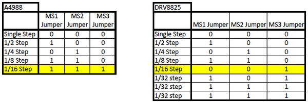
The usual setting of 1/16 step is highlighted, so we are going to put a jumper in all three positions, MS1, MS2, & MS3. Do so for all 4 drivers, notice the drivers cover these jumpers so do it now! The image below shows 1/16 micro stepping set for each driver. Note the jumpers circled in green. I didn’t worry about the E1 socket or jumper as I only have one extruder on this build.
3) Install Drivers:
See below the 4 A4988 Drivers installed. In positions X, Y Z, and E0

Careful, they fit in backwards as well! See below highlighted both an ‘en’ and ‘dir’ pin.
This stands for direction and enable, not so interesting aside from the fact that these are also marked on the ramps board so you must match them up!

Don’t forget your heat sinks!!! Be careful the heat sink doesn’t foul the trim pot or other solder joints that it sits near.

4) Powering the ramps shield.
NOTE: AT THIS POINT WE DON’T ACTUALLY TURN THE POWER ON!
You’ll likely be using a 12 volt DC power supply of some sort. Make sure it’s powerful enough to do the job. Your printer likely requires allot of power. The kind of power supplies you find at Jaycar are not going to do the trick. We use 400W supplies, you need at least ½ that for a small printer, the 300x300mm shipped with some 3DTek.xyz Ordbots will most all of it.
Make sure your wire is of a low enough gauge to handle the current! This is important.
The images below shows a standard power setup.


If you are sure your wire can handle the current, you can simply jump the power over at the connector as per the image below. Think before you do this, and if your power supply has two outputs, check if they are the same output or isolated from each other hen considering how to power the board.

- Use an appropriate gauge wire for the current you will be using.
- Don’t have bare copper extending out of the connector
- Don’t let the wires insulation enter the conductive jaws of the connector, high resistance joints are bad.
- Disconnect the green power plugs now; it will be a while before we need power;)
5) Connect your motors.
As mentioned before, you need to be aware of which wires form the two pairs / coils of your stepper motors. Read about stepper motors in the introduction if your not sure.
3Dtek.xyz customers – Pair 1: Green & Black, Pair 2: Red & Blue
Install your motors in the printer and route the wires as you choose all the way to the point that your electronics will be mounted. 3DTek.xyz customers have been supplied with enough cabling to get all the wiring off the printer into an external electronics enclosure.
If you chose to use the sockets in step one then we now need to install the plugs on to the end of the motor wires. Otherwise solder on what ever connection you went for.
The most important thing is that your pairs are in the right spot! Make sure one pair goes into the two pins on one side of the plug and the other into the other side of the plug. It doesn’t matter if what order they go in right now, as long as pins one and two are one pair and three and four are the other (counting from either side of the plug)
Terminate to your desired connector; 3DTek.xyz customers solder your motor wires to the fly leads on the supplied plug, observing the warnings about keeping pairs together. See this short video I made for you about soldering quickly and cleanly.
A very good guide can be found here:
http://www.geeetech.com/wiki/index.php/Ramps1.4
6) Connect Limit Switches
Generally printer kits use the Reprap discount style limit switches. We are only using one of them and two Omron lever switches. There are special end stops designed for use in the Ordbot however we have not been able to source them for some time.

You can use the twisted pair for the end stops. It was supplied with cuts in the outer sleeve so you can slip of the sleeve and pull out the individual pairs.
The Red Omron Lever switches have 3 terminals, we use the terminal on its own on the side of the switch and the closes of the two other terminals as shown in in the left of the photo below. For the ramps PCB mounted switches we will use the two top wires (note the photo below right – the switch is upside down)
Your end stops have no polarity either, they are simply a switch. When depressed they will short a pin on the Arduino to ground which lets the software know its hit a limit.
This images below show which two pins on the omron and reprap limit switches are to be used. On the left is the X axis limit switch in the supplied mount, on the right the Z axis switch in supplied mount.

The photo below clearly shows where your twisted pair wires from each limit switch end up on the Ramps Board

The Y limit switch sits on a supplied printed mount, which bolts to the Y-axis makerslide. It is triggered by a brass or nylon standoff (supplied) that will need to be carefully measured and a hole drilled in the y carriage so that the standoff can be mounted in a way that it fouls the switch at the correct moment and limits any further travel.
7) Connect Heated Bed
4 different beds are supplied with the 3DTek.xyz ordbots:
- 200mm red pcb beds – require glass or other surface on top to print on
- 200mm Aluminium black direct print heat beds
- 250mm heat beds – require glass or other surface on top to print on
- 300mm heat beds – require glass or other surface on top to print on
The 200mm beds can be connected directly to the ramps 1.4 board – connector D08.
The 250 and 300mm Beds may require a relay. 3DTek.xyz have destroyed the power circuitry on several ramps boards, we suspect through not using the relay, and so are supplying 30 amp 12v coil relays to run the larger heat beds.
The relays should be configured so that when its coil is powered by the D08 connector it closes and passes supply power from the power supply to the heat bed. The larger heat beds can draw significant current on startup and by using the relay this should avoid any potential damage to the ramps circuitry.
The heated bed will require a thermistor to help manage its temperature; this is taped to the bottom of the heated bed in the center with Kapton or other heatproof tape and connected to the Ramps T1 pins. No polarity to observe for the thermistor. The thermistors two wires are not insulated, you have been supplied a heatproof insulator to slide over the bare copper wires, slide it all the way up so they cant touch.

8) Connect Hot End / Extruder
In addition to the extruder stepper motor, you typically have 2 other sets of wire going to the extruder/hot-end: the hot-end thermistor, and the hot-end power resistor (or cartridge heater).
The hot-end power heater (or cartridge heater) connects to the D10 connector on the RAMPS board. This is also prewired on the combined hot end extruder.
Again no polarity here. The hot end will require a significant gauge wire; 3DTek.xyz customers use the smaller of the two sets of Silicon wire supplied. This connected to D10 – no polarity to observe here.
The hot ends thermistor is generally pre wired to the hot end in our case and connected to T0 on the ramps board, no polarity to observe here either.
Some 3DTek.xyz supplied hot ends had been mistakenly supplied with a thermocouple not a thermistor – these are not interchangeable and should be contacted if you have not already had a fix posted to you. Its easy to discover if you have the thermistor or thermocouple, test the wires with a Multi meter and if you see approx. 100k ohms you are good with a thermistor, if you see significantly less then you will need to contact 3DTek.xyz on [email protected] – you will be sent the thermistor ASAP.
9) Software & Firmware
Regardless of your choice of firmware and software, you will need AVRDude.
The easiest way is to just install the Arduino software, it will manage the AVR dude bit for you and keep you away from the command line!
Again from here you may well deviate completely.
3DTek.xyz’s preferred firmware is Repetier, its marlin essentially but modified slightly.
There are many choices for you, many of them tested and documented online. If you think you may need to call on 3DTek.xyz support then use the method outlined below. Other software / firmware choices are great however you will be on your own with the evaluation and testing.
Download the Repetier host for Mac or PC: http://www.repetier.com/
Download the 3DTek.xyz printer test configuration.
Save this file, extract it then copy the ‘Repetier-Firmware 2’ folder into your Arduino folder – it may be in a different place depending on how you installed it. If unknown, open Arduino and choose save as to see where it looks to save a file.
Plug in the Arduino via supplied usb cable.
From the Arduino interface, under tools =>gt; serial port, choose the serial port that your Arduino came up as using.
Under tools => board, choose ‘Arduino Mega 2560 or mega ADK’
Open the file you downloaded (Arduino calls them sketches)
Click upload, if all is well after a short while you have successfully uploaded the code to your Arduino, you will notice at this point the LCD screen becomes active.
Then look to the configuration tool. http://www.repetier.com/firmware/v091/
This handy webpage takes your parameters and creates a modified configuration file for you to load into the Arduino, it keeps you from having to read through and edit the code yourself and for the beginner is a great helping hand.
You can offer the configuration tool your previous configuration.h file (its in the folder you downloaded and saved into arduino folder) and it will incorporate your prior configurations into the helper so that you can simply update a single parameter and not start from scratch each time.
There are heaps of parameters to play with in here, test them all and see what works best for you. There are so many parameters for 3d printers that we cannot go into them all here. What you are mainly interested in are the motor directions, limit switch configurations, thermistor types and heated bed management plans.
From this point some reading over the repetier documentation is required for both the fine tuning of your printer and the cam processing & print workflow you will use to print your parts.
http://www.repetier.com/documentation/repetier-host/rh-installation-and-configuration/
Please contact 3DTek.xyz on [email protected] at anytime with any questions or comments on this guide or your Ordbot printer.