
XYZ Carve Build Instructions

8.Base Frame
Base Frame.
How to view the animation? Autodesk embedded models have been having some issues, if you cannot view the model below please click Here
Best viewed in full screen using the button at the right of the bottom toolbar.
Best viewed in full screen using the
 button at the right of the bottom toolbar.
Notes Before you start:
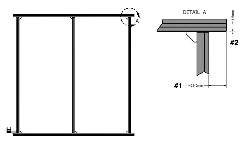
- There are 5 sections of 2020 T-Slot extrusions. Two will be slightly longer and are aligned with the X Axis which is left to right when viewing the machine from the front. The three shorter pieces align with the Y axis which runs front to back.
- Install the right angle gussets, however, do not tighten them up yet, they will be tightened after installing the Y axis and Gantry.
- The longer horizontal (X) 2020 extrusions overlap the shorter vertical (Y) 2020 extrusions by approximately 29mm
- The shorter vertical (Y) 2020 extrusions do not butt right up to the longer horizontal (X) 2020 extrusions, there is approximately 1.5mm gap
- Do not concern with dimensions and tightening up gusset joints, these will need to be adjusted when installing the Y Axis, Gantry and Waste board.
- Note: The 3 Shorter 2020 extrusions are around 958mm, this added the the 2 x 20mm widths of the longer extrusions is only 998mm, so there will be ~ 2mm gap once assembled. This gap will be set by the length of the Y rails during Y rail installation.
Autodesk embedded models have been having some issues, if you cannot view the model below please click Here
Best viewed in full screen using the button at the right of the bottom toolbar.
Base Frame BOM:
| Qty | Part | Image | |
| 2 | 2020 Base (X axis length – 43mm) |  | |
| 3 | 2020 Base (Y_Axis) |  | |
| 1 | Drag Chain Support Bracket 3 | 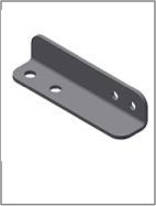 | |
| 14 | Socket Button Head Cap Screw – M5 x 0.8 x 8 |  | |
| 27 | Tee Nuts Mix of Pre and Post Assembly | 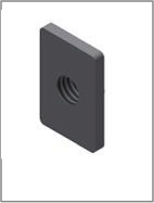 | |
| 2 | Socket Flat Countersunk Head Cap Screws – M4x10 |  | |
| 2 | Prevailing Torque Hex Nut – M4 x 0.7 | 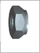 | |
| 1 | Drag Chain End Male | 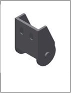 | |
| 6 | 2020 Right Angle Gusset |  | |
1 of 1 users found this section helpful