
Thank you for purchasing a 3DTek.xyz Heavy Mill.
Please allow for several solid days in build and tune to get the Heavy Mill ready for use. Don’t rush – try to enjoy the build process.
Having an online guide will enable the use of videos and easily updated content. If there is any part of this build you think needs more documentation attention or clarification – please email [email protected] or place a comment in the new Heavy Mill area of the discussion forum.
Precautions
- Please note – this is not an appliance – it is an industrial tool.
- The construction and use of this machine pose many hazards to your safety.
- This is not a tool to be left running unintended, as you would not leave any other power tool operating in your absence.
- As for all power tools, Lose clothing/hair etc should be secured before approaching the machine.
- Get used to wearing glasses when in the vicinity of this machine. Milling bits and other debris do get thrown from the machine.
ELECTRIC SHOCK!
The VFD, and power supplies pose a significant risk to your safety.
- A licensed electrician should commission these items.
- These items should be enclosed in a grounded or otherwise appropriate enclosure and kept clean of dust and moisture.
- The machine should be installed on a circuit that is protected by an RCD and breaker
VFD (Variable Frequency Drive) also Known as VSD (Variable Speed Drive) varies the frequency of the output from the 50hz its supplied to within the range of 0-400HZ in order to manage the speed of the spindle.
This device has large capacitors, which can hold a charge for quite some time. Your electrician must commission this and the other power supplies on your behalf.
Kit Contents
Contents of the kits vary depending on the options selected at the time of purchase.
The base kit consists of:
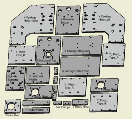
Anodized Plates:
| Plate Parts | Description | QTY |
| SCP | Spindle Carriage | 1 |
| YPA | Y_Plate_Type_A | 2 |
| YPB | Y_Plate_Type_B | 2 |
| XHP_Top | X Horizontal Top | 1 |
| XVP_Front | X Carriage Plate Vertical Front | 1 |
| XVP_Back | X Carriage Plate Vertical Back | 1 |
| XHP_Bot | X Horizontal Bottom | 1 |
| XHP_Mid | X Horizontal Mid | 1 |
| XMP | X Motor Plate | 1 |
| YMP | Y Motor Plate | 2 |
| XPP | X Pulley Plate | 1 |
| YPP | Y Pulley Plate | 2 |
| BCT | Belt Clamp Top | 3 |
| BCB | Belt Clamp Bottom | 3 |
| YCP | Y Carriage Plate Left | 1 |
| YCP | Y Carriage Plate Right | 1 |
| YCP | Z Motor Mount | 1 |
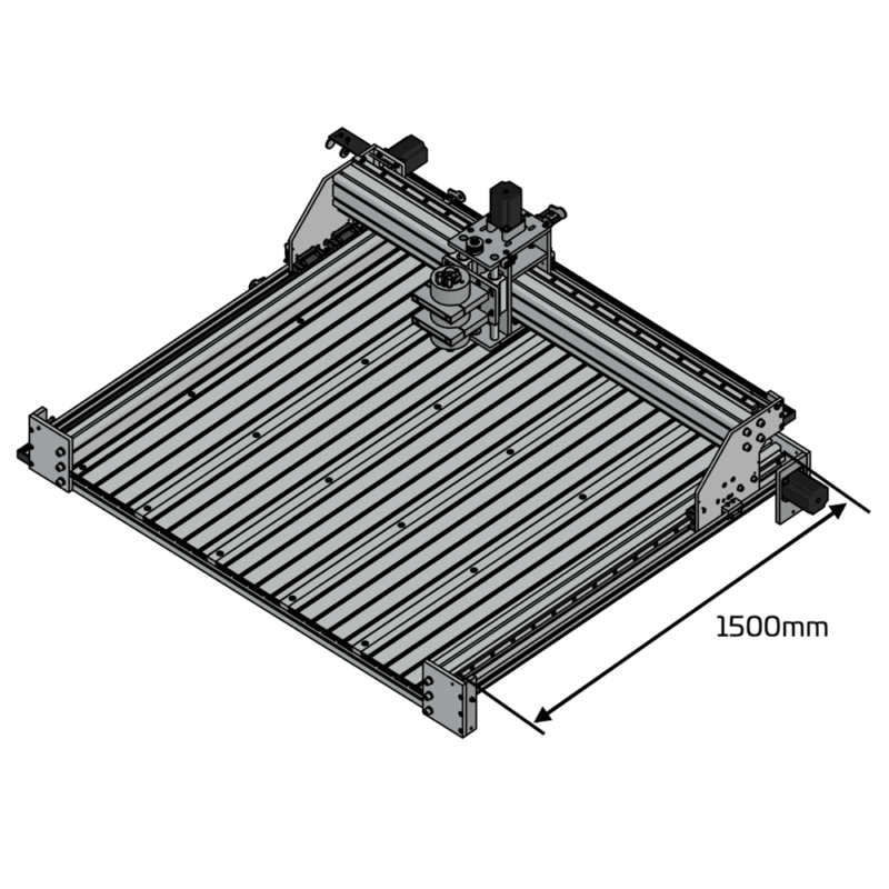
Aluminium Extrusions:
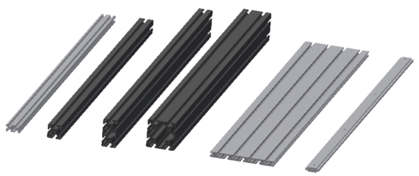
| Part | Description | 1000mm Qty | 1500mm Qty |
| 4040 Rail | 4040 Rail – Base Structure | 4 | 6 |
| X-Axis Rail | 8080 – Tapped Both Ends M8 * 15mm | 1 | 1 |
| Y-Axis Rails | 40120 – Tapped Both Ends M8 * 15mm + Drilled & Counterbored holes. | 2 | 2 |
| XDGRail | X-Axis Drag Chain Support Rail 2040 T Slot | 1 | 1 |
| YDGRail | Y-Axis Drag Chain Support Rail 2040 T-slot | 1 | 1 |
If you chose the T-Slot bed option, the following extrusions will also be included
| Part | Description | 1000mm Qty | 1500mm Qty |
| Bed T-slot | 15180 – T-slot Bed Extrusion – If bed option is taken | 3 | 5 |
| Bed T-slot Left Side | 15180 – 4-6 holes – if bed option taken | 1 | 1 |
| Bed T-slot Righ Side | 15180 – 4-6 holes – if bed option taken | 1 | 1 |
| T-Slot Tee Extrusion | T-Slot Connectors – if bed option taken | 4 | 6 |
Water Block Strip | 12×3 MM Alloy Flat Bar strip – if bed option taken | 1 | 1 |
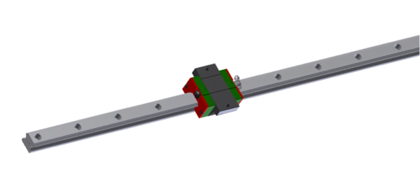
Linear Motion
| Part | Description | 1000mm Qty | 1500mm Qty |
| HGW20 | HGW20CC Linear Bearing Blocks | 6 | 6 |
| HG20 | Linear Rail – ~990 / ~1490 mm | 2 | 2 |
| HG20 | Linear Rail – ~1100 / ~1490 mm | 2 | 2 |
| Part | Description | 1000mm Qty | 1500mm Qty |
|---|---|---|---|
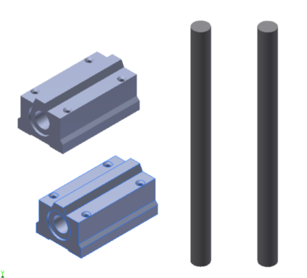
| HSS | 16mm hardened Steel Shaft 225mm | 2 | 2 |
| PB | Pillow Bearing Blocks SC16LUU | 2 | 2 |
Hardware
| Part/Purpose | Label Code | Qty |
| Securing Z Pully on Acme Thread | M8 Flanged Nut | 1 |
| 8MM Steel Spacer sits below pulley on Z Acme | 8 mm Spacer | 1 |
| Idler Pulley Spacer 5mm Bore (one inside, one outside Idler) | 3 mm Spacer | 6 |
| Z-Axis Lead Nut | Lead Nut | 1 |
| X & Y Limit switches | M3 Nylock Nut | 8 |
| X & Y Limit switches | M3 Washer | 8 |
| Shaft Grubs Screws | M3x10 BHCS | 4 |
| Z Limit Switch | M3x16 SHCS | 2 |
| X & Y Limit switches | M3x25 SHCS | 8 |
| Drag Chain to Drag Chain Support Extrusion | M4 Tee Nut | 4 |
| Drag Chain to Drag Chain Support Extrusion | M4x10-12 SFHCS | 4 |
| Drag Chain Mounts | M5x12 BHCS | 4 |
| Belt Clamp Top | M4x25 SHCS | 6 |
| Stepper Motors | M5 Nylock Nut | 24 |
| Stepper Motors | M5 Star Washer | 16 |
| Stepper Motors | M5 Washer | 16 |
| Y Stepper Motors | M5x25 SHCS | 8 |
| Z Motor Mounting | M5x16 BHCS | 12 |
| Securing Bearing Rail, X Stepper Motor | M5x20 SHCS | 104 |
| Bolting together all other plate hardware | M5x20 FSHCS | 28 |
| Motor Plates, Pulley Plates | M5x20 FSHCS | 18 |
| Belt Clamp Bottom | M5x25 BHCS | 6 |
| Idler Pulley Axels | M5x30 BHCS | 3 |
| Y-Axis Limit Switch Triggers | M5x40 BHCS | 2 |
| X-Axis Limit Switch Triggers | M5x70 SHCS | 2 |
| Bearings In Y-Axis | M6 Spring Washer | 16 |
| Bearings In Y-Axis | M6 Star Washer | 16 |
| Bearings In Y-Axis | M6x20 SHCS | 20 |
| Bearings In X-Axis Plates | M6x20 FSHCS | 8 |
| Securing Wasteboard | M6 Tee Nut | 30 |
| Spindle Clamp Bolts | M6x50 SHCS | 4 |
| Y Plates to X-Axis Extrusion / End Plates to Y Extrusion, Spindle Mount | M8 Spring Washer | 24 |
| Y Plates to X-Axis Extrusion / End Plates to Y Extrusion, Spindle Mount | M8 Star Washer | 24 |
| Y Plates to X-Axis Extrusion / End Plates to Y Extrusion, Spindle Mount | M8x25 SHCS- | 24 |
| Securing Y Rails to Base | M8x40 SHCS | 12 |
Other Parts
| Part | Description | 1000mm Qty | 1500mm Qty |
|---|---|---|---|
| T5B10 | T5_Delrin Idler | 3 | 3 |
| DC | Drag Chain / m | 3 | 3 |
| Z ACME | Z-Axis Acme Thread 202mm | 1 | 1 |
| T5P10 | T5 Pulley 10-15 tooth With flange | 4 | 4 |
| T5P20 | T5 Pulley 20-24 tooth With flange | 1 | 1 |
| FB | Flanged Bearing | 2 | 2 |
| CN | Coolant Nozzle (T-slot Bed Option Only) | 1 | 1 |
| MBC | Misumi Black Cap 2040 | 4 | 4 |
| Gusset Set for 4040 | Set of 8 Gussets | 1 | 1 |
| Spindle | None, 800W, 1.5 KW, 2.2kw as per option selected | 1 | 1 |
| Spindle Mount | 80mm Spindle Mounts if spindle option selected | 1 | 1 |
| NEMA23_76 | Stepper Motors Nema 23 – 76mm Single Shaft | 4 | 4 |
| CP | Coolant Pump (Qty 2 if T-slot bed option is taken) | 1 | 1 |
| Belt | AT5 Open Belt – meters | 7.5 | 10 |
| Belt | AT5 Closed Loop Belt | 1 | 1 |
| DT | Drip Tray – (With T-slot Bed Option) | 990 | 1400 |
| DCB | Drag Chain Brackets2 | 2 | 2 |
Things you will need to complete the build
- Soldering Iron
- Basic Hand Tools
- A couple of tubes of clear kitchen/bathroom silicone (T-slot Bed Option)
- Support from an Electrician to commission the 240V components.
Electronic Components
Depending on the options you have selected the electronics kit may include one of the following:
- GRBL AIO & Associated Connectors
- Masso Controller & Associated Connectors
- Gecko G540 Driver Board & Associated Connectors / Cooler Etc
All Kits include a minimum of the following Electronics
| Description | Qty |
| Electronics Enclosure | 1 |
| Neutrik PowerCon Plug & Socket | 1 |
| Din Rail | 1 |
| 12V Power Supply | 1 |
| 12V Fan & 2 * Dust Filter | 1 |
| Cable Ties & Sticky Mounts | Assorted |
| DC PSU Cable | 1m |
| 2.5mm AC Power Cable Red, Black, Green | 1m |
| Wiring harness Motors | 4 |
| X&Y limit cables Harness | 2 |
| Z limit cable Harness | 1 |
| Emergency stop switch | 1 |
| Large cable gland | 2 |
| Medium cable gland | 2 |
| Small cable gland | 2 |
| Cable Sock | 5 |
| Large Cable Sock | 10m |
| Medium Cable Sock | 2m |
| Small Cable Sock | 2m |
| Variable Frequency/Speed Drive /(With Spindle Option Only) | 0/1 |
| 12V Bilge Pump (Water Cooled Spindles Only) | 0/1 |
| 2 x DC Power supplies, electronics option dependant | 2 |
| Shielded 4 Core VFD Spindle Cable | 7m |
Variable Frequency/Speed Drive (VFD / VSD)
Your inverter must be installed by a Licensed Electrician – these notes are for the electrician.
Notes:
- Your inverter must have a ground connection.
- Your spindle will die, very quickly, without coolant flow, don’t run it without first setting up the coolant pump! (Relevant to Water Cooled Models Only)
- Setup the VFD parameters before running the spindle!
- There is no polarity to the spindle connections. Active outputs from the VFD connect to any of pins 1, 2 & 3 on the Spindle. The Spindle will run in an arbitrary direction. You want it to run clockwise when looking from above. (Above when the spindle is mounted!). If the spindle is not turning clockwise, you can simply swap over any two of the 3 active spindle connections at either end. Just pick two of the three active wires and swap them, clearly not the ground line it must stay connected to pin 4 on the spindle.
- Shielded Cable is provided to help keep this noisy appliance from interfering with the limit switch signal lines.
- The front panel of the VFD can be removed and a PC network cable used to mount the control panel in a convenient place.
- Do not run the spindle without first ensuring the coolant is flowing to it(water-cooled only) and setting these parameters!
Heavy Mill Assembly.
- The assembly of your Heavy Mill is not overly dependent on the order.
- Please set the short videos on loop as you assemble each part.
- The pre-build notes in the next section may save a lot of difficulties, read before starting assembly
Regarding Hardware:
- As a general rule, if it fits its the right bolt, nut or screw – it will fit don’t force it
- There are several washer types included which provide different support. The Spring Washers help maintain pressure on the joint to reduce vibrations loosening the connection and the star washers to help keep the assembly in a position where the bolt may be in a slot and not a hole. We tend to use both a star and a spring in the slotted holes – although this may be unorthodox.
- There are considerable spares included, you should not need to find a hole for all of these
- Following the short videos and cross-referencing the hardware list above to select the right hardware for the assembly.
Regarding Electronics:
- It’s very important to have electricians support for commissioning.
- The VFD cable supplied is an important part – its difficult to make use of such a thick cable however it has been designed for the tough job and should not be substituted.
Pre Build Notes:
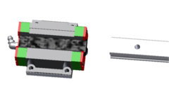
The Linear Bearing blocks used on the X & Y axis need to be carefully installed.
There is a small black spacer inserted into the bearing, it’s not to be pulled out – doing so will release all the balls all over the floor and repacking is quite an episode. Never remove the black spacer strip unless it’s a rail that’s pushing it out and taking its place!
The tolerances of these bearings are very tight. Where two bearing blocks must be used together the bolts securing the bearing blocks must be left loose. Should the bolts be tight and there be no play in the alignment of the blocks, the rail will not be able to be slid through both blocks. In the image below as the rail attempts to enter the second block – it had better be perfectly aligned or left loose. Otherwise at this point will need to be backed out and realigned and it’s a tough job to feed the black spacers back into the blocks carefully while retrieving a heavy rail out of the block!
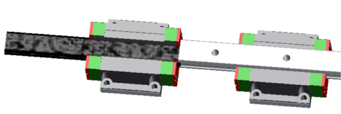
CAD Video of how the install and remove rails without loosing balls
Stepper Motors
- Never disassemble the stepper motors, after doing so they are ruined – if something is wrong with a stepper, its wiring or driver-based – nothing can be fixed by opening the motor.