
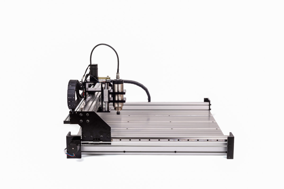
Base Construction
The Heavy Mill base consists of 4 to 6 x 40*40 cross extrusions and 2 x 40*120 Y Extrusions.
1000mm:
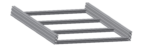
Parts List for 1000mm Base:
- 4 x 40*40 Base Supports
- 2 x 40*120 Y Rails
- 8 x M8*40mm SHCS
- 4 x T-Slot Connectors (With T-slot Base option only)
- 20 x m6 Tee Nut (With T-slot Base option only)
- 20 x M6x25 FHCS (With T-slot Base option only)
1500mm:
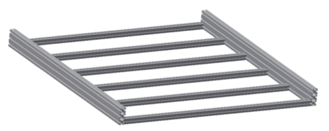
Parts List for 1500mm Base
- 6 x 40*40 Base Supports
- 2 x 40*120 Y Rails
- 12 x M8*40mm SHCS
- 6 x T-Slot Connector (With T-slot Base option only)
- 30 x m6 Tee Nut (With T-slot Base option only)
- 30 x M6x25 FHCS (With T-slot Base option only)
Custom Size Heavy Mills: ***
Parts List for Custom Base
- Custom qty of 40*40 Base Supports
- 2 x 40*120 Y Rails
- Gussets for base construction
*** Note
- Custom Heavy Mill Sizes ship with a custom qty of 90 Degree Gussets rather than M8 bolts for assembly
- 4040 Base supports to be set with even spacing along Y Rails.
CAD Assembly of the base
X/Z Axis Setup

X/Z Axis Parts
| Part Description | Quantity | |
| HGW20CC Linear Bearing Blocks | 2 | |
| Hardened Steel Shaft | 2 | |
| X Carriage Vertical Front | 1 | |
| X Carriage Vertical Back | 1 | |
| M5x20 FSHCS | 32 | |
| Flanged Bearing | 2 | |
| Z-Axis Acme Thread | 1 | |
| AT5 Belt Loop | 1 | |
| Limit Switch With Lever | 2 | |
| Limit Switch No Lever | 1 | |
| Belt Clamp Bottom | 1 | |
| Belt Clamp Top | 1 | |
| M4x25 SHCS | 2 | |
| X Carriage Horizontal Mid | 1 | |
| X Carriage Horizontal Bottom | 1 | |
| M6x20 FSHCS | 12 | |
| Drag Chain Bracket | 1 | |
| M5x12 BHCS | 2 | |
| M3x25 SHCS | 4 | |
| M3x16 SHCS | 2 | |
| X Carriage Horizontal Top | 1 | |
| NEMA 23 Stepper Motor | 1 | |
| 8MM Steel Spacer for Acme Pulley | 1 | |
| Z Motor Mount | 1 | |
| Pillow Block Bearings SC16LUU | 2 | |
| Spindle | 1 | |
| Z-Axis Lead Nut | 1 | |
| Spindle Mount Front | 2 | |
| Spindle Mount Back | 2 | |
| Spindle Carriage Plate | 1 | |
| M5x16 SHCS | 8 | |
| M8 Flanged Nut | 1 | |
| Drag Chain end link | 1 | |
| AT5 Pulley 10 | 1 | |
| AT5 Pulley 20 | 1 | |
| Pulley Grub Screws | 4 | |
| M3x10 BHCS | 4 | |
| M4x10 SFHCS | 2 | |
| M5x25 BHCS | 2 | |
| M6x50 SHCS | 4 |
Notes:
- DO NOT remove the black tabs from inside the bearing blocks!!
- The bearing blocks are not directly in line with each other, one is offset.
- There are 3 horizontal plates and two verticals.
- All plate screws are Countersunk M5 * 20’s
- The HGW20 bearing blocks take M6 countersinks (leave them loose)
- Do install the Flanged Bearings, Acme Thread, Hardened Shafts and Pillow Block bearings at this time so that it doesn’t have to come apart during the installation of the Z-Axis.
- The tolerance of the 6 holes for the shafts and flanged bearings is very tight! You may have to lightly sand the inside of the holes with some emery cloth or tap with a soft to install the shafts and bearings, this is a pain but by design and necessary.
- The Star washers will help the Z motor grip in its slots, install at the closest point to the front, put on AT5 closed belt on then pull back tight and lock-off nuts.
- Once complete you can add the Z-Axis parts as well as the main X 8080 rail. Watch the Video: Z-Axis – Spindle Explosion
- In the CAD Assembly video below, the 4 spacers holding the Stepper motor have now been replaced with a single Z Motor Mount plate using 8 x M5x16mm bolts to secure – 4 from below, 4 from above
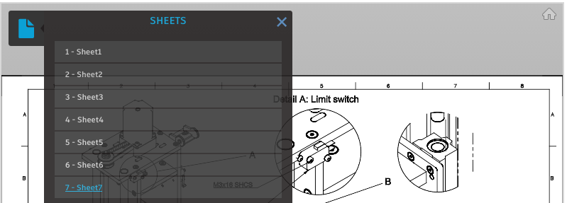
XZ Axis Drawings –
NOTE – THERE ARE MULTIPLE DRAWING SHEETS Click the page icon in the top left of this embedded document to view additional sheets
X-Axis Linear Rails
Notes:
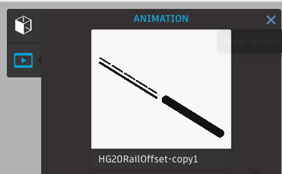
- When installing the Linear rails, note that they are offset as per the image below.
- Do not install the green dust plugs into the bearing rails – this should be left until the end of the build
- Do not tighten any bearing rail bolts until such time as the X-axis belts are being lined up. Only enough so that the bolts do not sit proud of the rail so that they will not catch the bearings when sliding along it.
Below an animation of the Bearing Rail installation. Please select the animation view as shown in the image below and then play from the bottom control bar.

X Rail Assembly Video
Y Plates Build and Gantry Installation
Notes:
- The remaining 2 x 20mm Linear rails are installed in the topmost channel of the main Y rails in the base frame using the Tee nut bars and M5x20 SHCS as per the X-Axis previously completed. Leave all bolts loose, tightening only enough to ensure bolt heads are not sitting proud of the rail which will cause them to foul a bearing sliding along the rail.
- Remember Again: Don’t tighten any bolts in the bearing blocks – must remain loose for alignment
- Take note when installing bearing blocks, they should be on the opposite side of the 3 vertical countersinks on the top of the Y plates as noted in the drawing below.
- Provided are M6 star and spring washers for the 20mm HGW20 bearing blocks. If using both, the star should be against the alloy plate and the split washer against the head of the bolt. One or the other washer can be left out.
- DO NOT remove the black bearing keepers from the bearing blocks, these are forced out when pushing the bearing onto the bearing rail.
- Don’t tighten up the bearing blocks still – leave them quite loose, failure to do so will ensure the bearings will not slide on and need to be reversed out… balls will hit the floor at this point unless you have extra hands to push the black bearing keepers back in as you pull back. SO ensure the two bearing blocks have plenty of wiggle/play before attempting to slide them onto the bearing rails. If in doubt, take the bearings off the Y plates and slide them onto the bearing rail one at a time then reattach the Y plate to the installed bearings.
Y Plate Explosion
There are two methods for installing the Gantry. The appropriate method will depend if you have a second person available to help.
Method 1: Solo
Whilst difficult it can be seen in the video below that a single person can install the gantry by first sliding the lone Y Plate assemblies onto the Y-axis bearing rails and then lifting and chocking the gantry X rail (with X/Z axis present) into place.
Method 2: With a helping set of hands.
The Y plate assemblies can first be attached to the gantry X Rail (with X/Z Axis also present) and then the entire assembly lifted and slid onto the awaiting Y bearing rails. Be sure to leave the 16 * M6x20 SHCS (attaching the bearings) very loose.
The drawing below shows the parts to attach the completed Y Plate assemblies to the gantry regardless.
Install Y Bearing Rails.
Notes:
- Place T nut bar behind the bearing rail and very loosely screw in the m5x20 SHCS.
- Slide entire bearing rail into Y-axis (in the top of the 3 Tee Slots).
- Lift the bearing rail high in the t-slot while tightening up the M5x20 SHCS.
- Do not install green dust plugs at this time.
Below a quick timelapse of the Y plates and gantry being installed. There is no commentary, shown simply for reference to see that lifting the gantry and holding it in place can be done at a pinch without help, however, is a little tough.