
Masso Setup. The Masso CNC Controller has some excellent resources: Documentation Video Tutorials Forum You can skim over most of the wiring information in the official documentation as the few wiring diagrams you have already followed will cover the wiring setup, the above links are for reference, you can move straight onto the list below. […]
13
Nov
Nov
Setup for GRBL AIO or GRBL Gecko-based controllers Step 1: Install USB Drivers Please download the latest Silicon Labs CP210X driver for your operating system. Operating systems supported OSX, Windows (XP,7,8,10) & Linux Note for OSX Users: You may receive a notice that the program ‘cannot be opened’, in which case you mist open preferences, […]
06
Oct
Oct
The default GRBL post-processor in Fusion 360 can sometimes cause a few issues when initially getting machines up and running. These being: A) machine runs off to home before starting (and at the end of a job) tripping a limit switch in the process, or B) the machine drags your endmill across the job […]
29
Aug
Aug
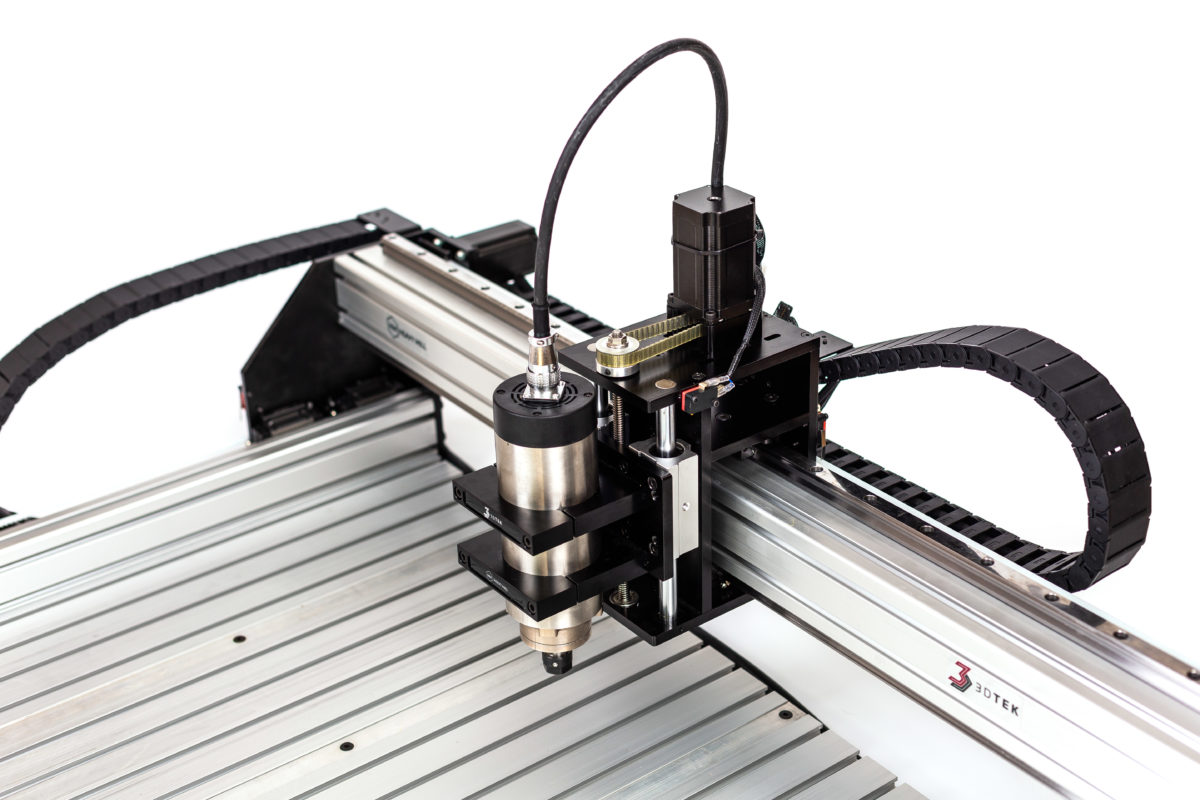
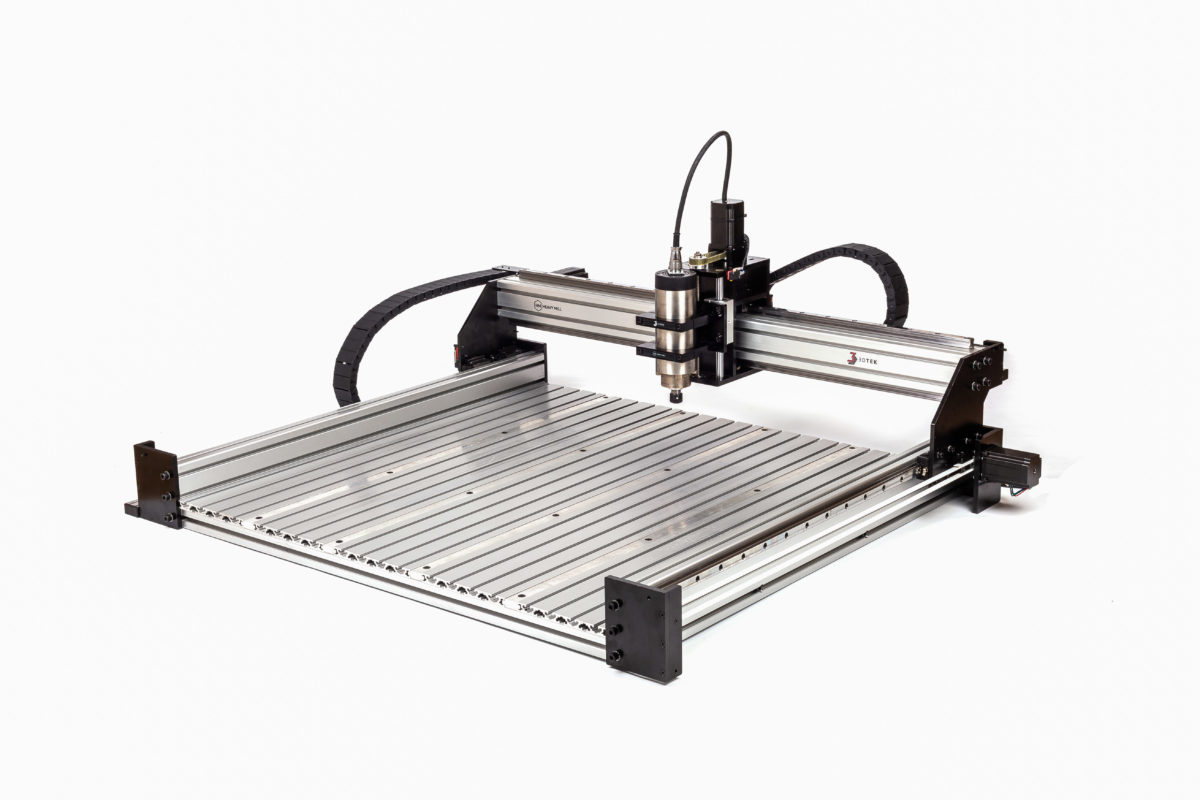
Y End Plate, Pulley Plate, Stepper Plate and Stepper Motor installation. Notes: Idler pulley plates and motor plates also have an extra hole for a screw that holds the drag chain support extrusions, these are installed with the hole at the bottom. There are 4 Y end plates, 2 x A-Type & 2 x B-Type. […]
08
Jul
Jul
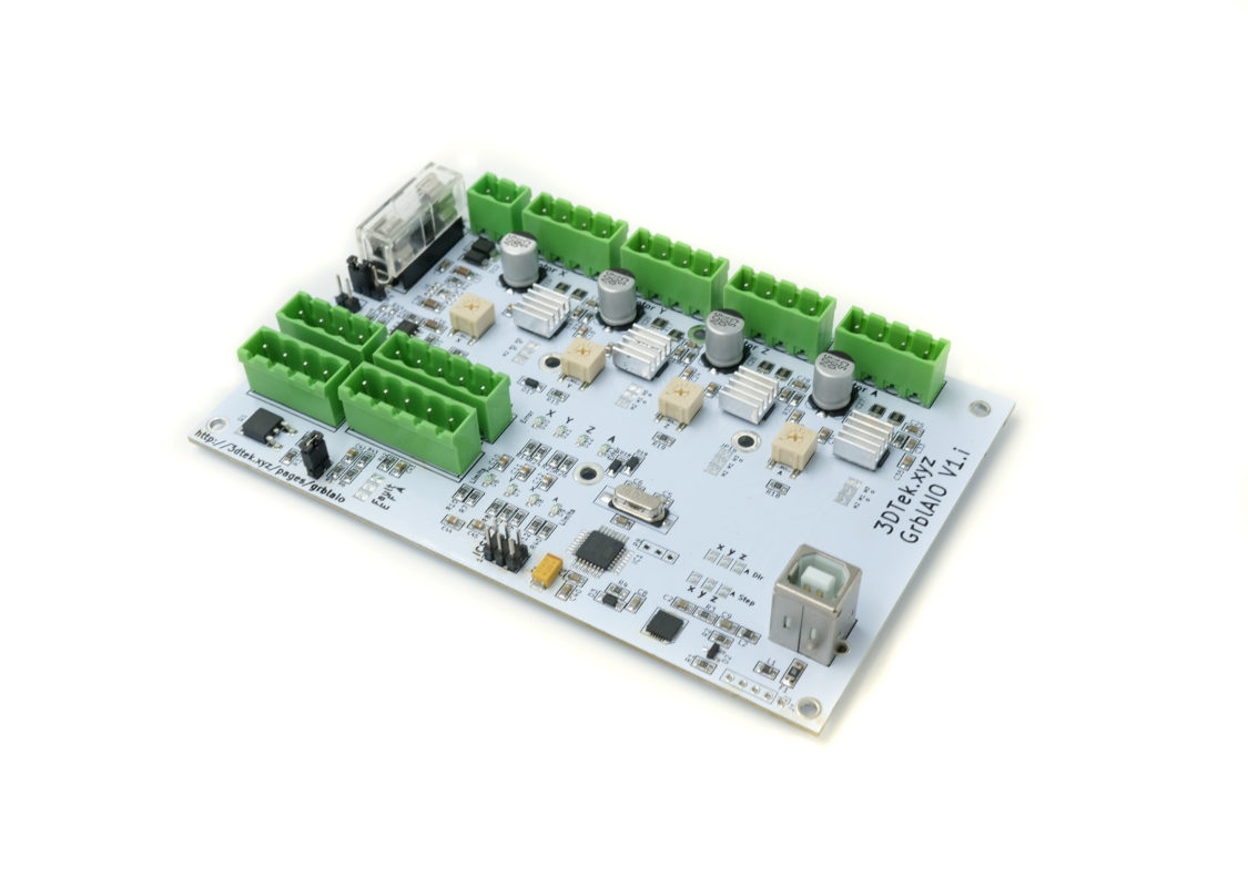
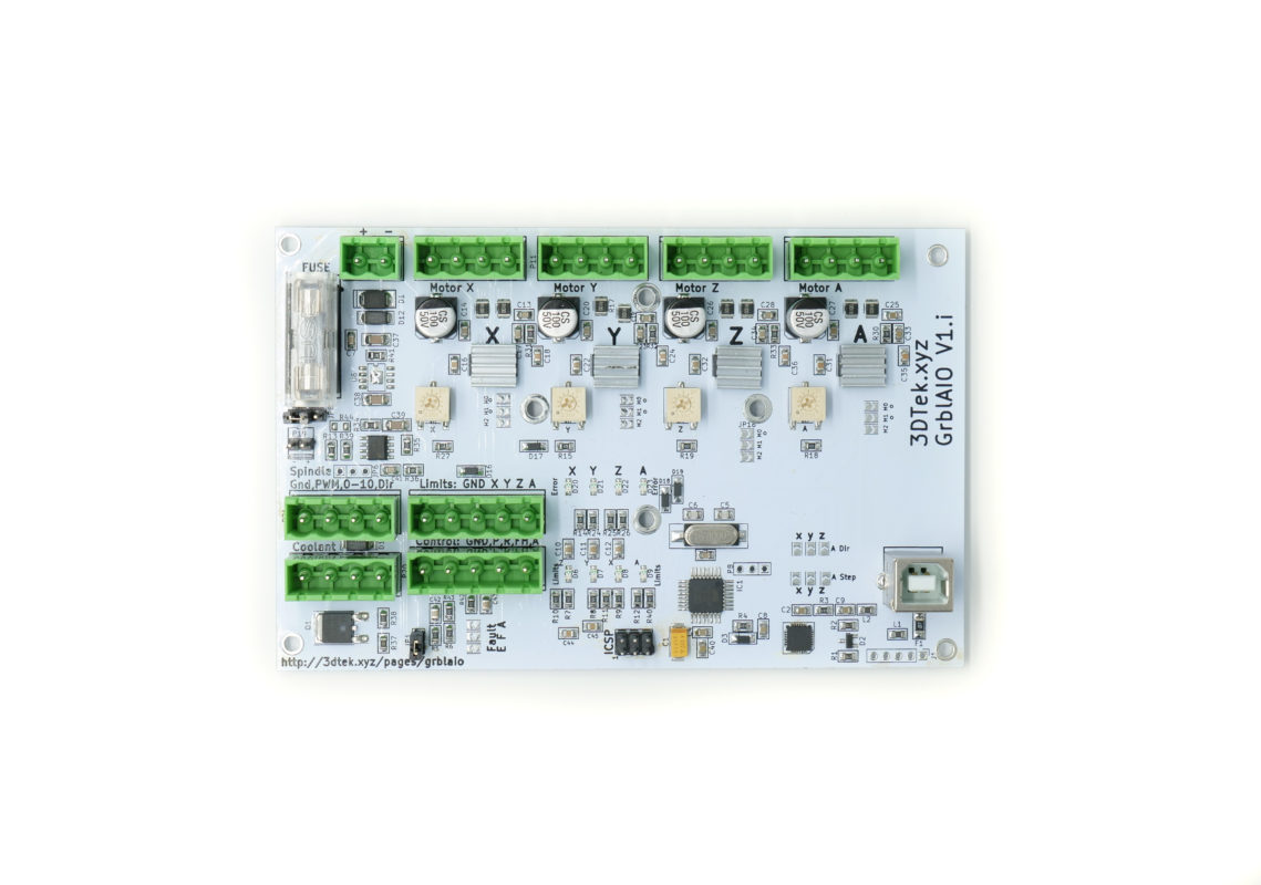
This post is about configuring the GRBL AIO Versions 1.G and EARLIER! – for versions 1.I + please see GRBL AIO Configuration Main Connections Detailed Fuse – 5x20mm – Suggested 10A 5mm Diameter x 20mm Length. This fuse acts on the 12-36V motor power circuit. 12-36V DC power in. The DRV8825 Drivers can actually handle up […]
20
May
May
Wiring diagrams for 3Dtek specific GRBL + Gecko G540 Combo. These may or may not be useful for other Gecko use cases. Please contact 3DTek for any assistance wiring up or configuring these devices. PLEASE READ IMPORTANT NOTES AT BOTTOM BEFORE POWERING UP THE VFD!!!! GRBL GECKO Power & INVERTEK VFD Connections GRBL GECKO Power […]
01
Mar
Mar
Below are the wiring diagrams for the Grbl Gecko Parallel Shield. Please contact 3DTek for any assistance wiring up or configuring these devices.
01
Mar
Mar
Wiring diagrams for 3DTEK VFD Spindle and AiO Card PLEASE READ IMPORTANT NOTES AT BOTTOM BEFORE POWERING UP THE VFD!!!! DO NOT POWER ON THE SPINDLE BEFORE FULLING CHECKING CURRENT SETTINGS ARE CORRECT IN THE VFD!!! These wiring diagrams take into account that a 0-10v signal will be supplied to the Invertek VFDs 3DTEK supply. […]

01
Mar
Mar
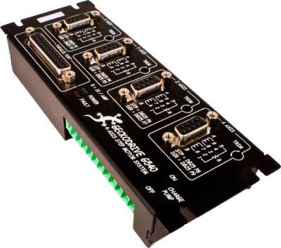
Diagrams Below are the wiring diagrams for 3Dtek specific Masso Applications. These may or may not be useful for other Masso use cases. Please contact 3DTek for any assistance wiring up or configuring these devices. MASSO POWER AND VFD CONNECTIONS MASSO LIMIT SWITCH WIRING Gecko G540 POWER Wiring GECKO G540 MOTOR WIRING Download Schematics For […]

01
Mar
Mar
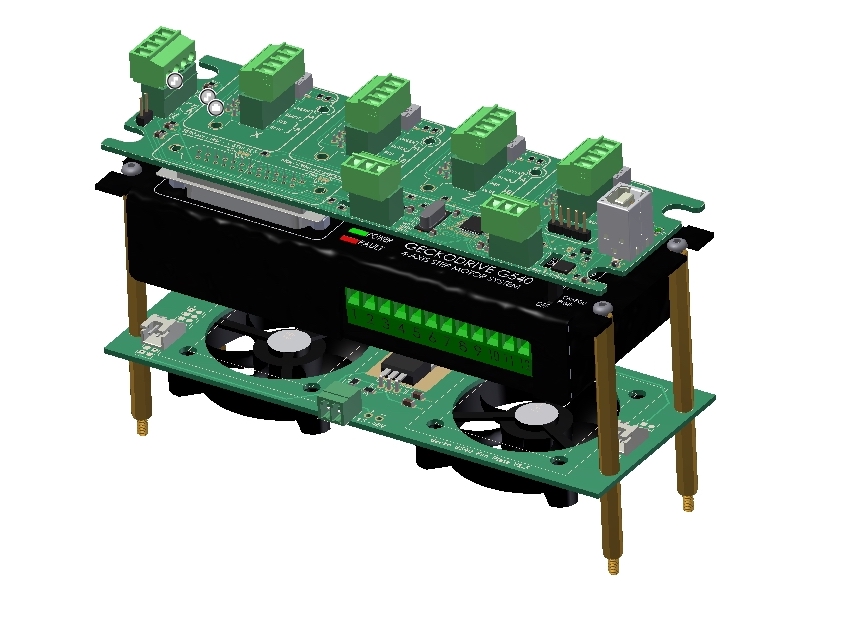
Below are the wiring diagrams for 3Dtek specific Gecko G540 Applications. These may or may not be useful for other Gecko use cases. Please contact 3DTek for any assistance wiring up or configuring these devices. Stepper Motor Connections (c) G540 Motor Connector Board Method< Stepper Motor Connections (b) GRBL -> G540 Motor Breakout Board Method […]